

Knowledge Base & Support
TOPICS
Auto Registration
Auto Registration will take a set of point clouds and automatically register or align them together based on a scan network.
This network can either come from the Vercator Field App or created manually in the web interface.
Job Creation
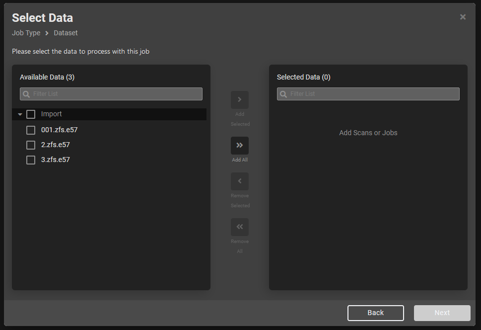
- From the Create New Job menu select Auto Registration
- Select the scans to be included on the left hand side with the checkboxes and choose ‘Add Selected’ or just press ‘Add All’ without selection as appropriate. Then press ‘Next’.
Scan Network
- Currently the registration algorithm must be given the network of scans to use for registration, with the network representing best overlap. This information is provided to the job by the user through the scan network tool during job setup. This process is easiest done by recording the rough placement of scans in the field using the Vercator App.
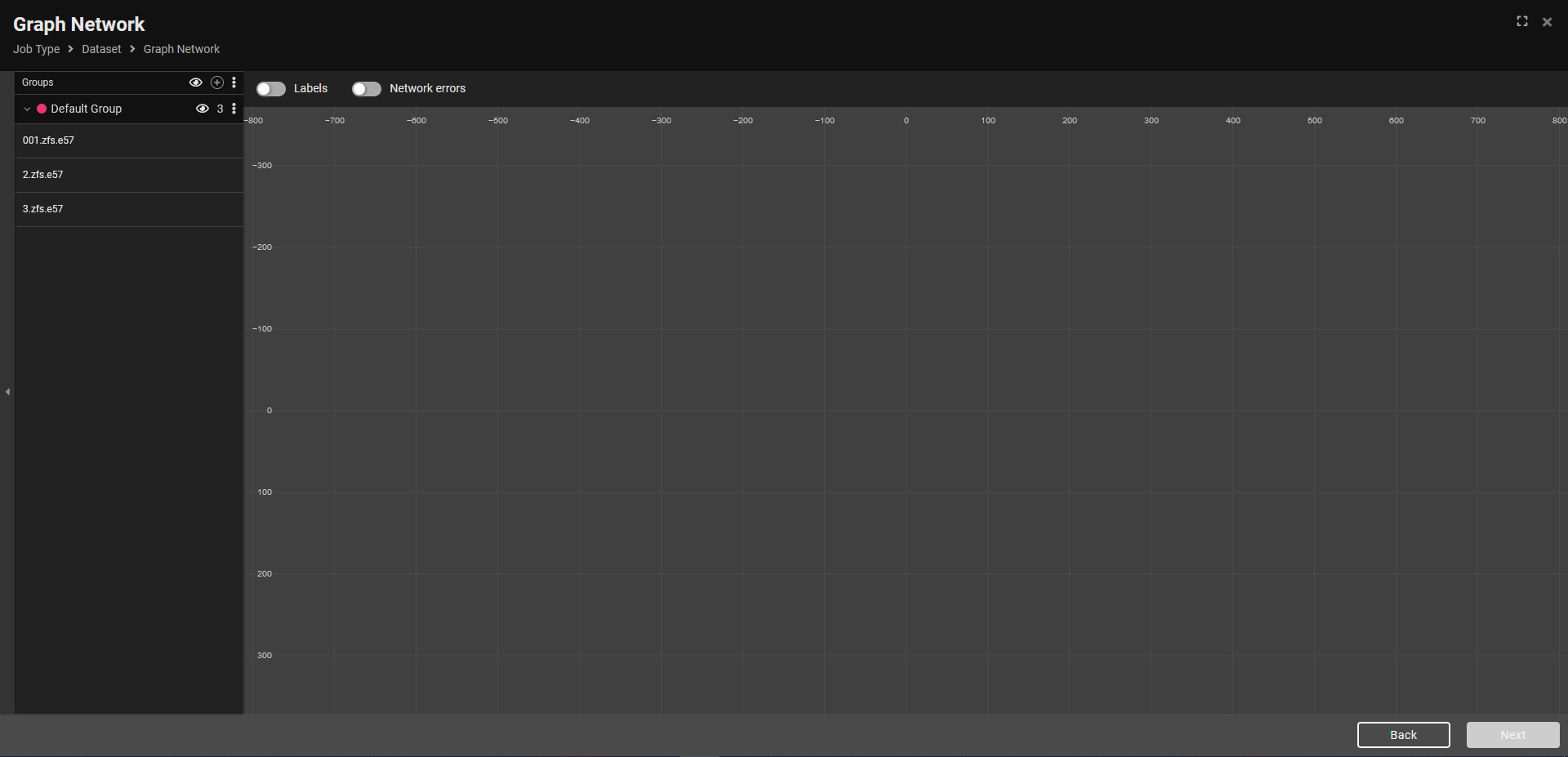
- The network interface has three main elements:
- Groups – for managing different layers of scans, such as floors in a building, groups can be created from the + symbol in the Groups title. Scans will be coloured by group.
- Scans – a list of the scans in the project to be placed. These get a small radial icon next to them when placed in the network plan.
- Network plan area – the canvas area on which scans are placed with a grid. This can be schematic and does not need to be spatially correct, it just needs to describe the best overlap.
Place Scans
- To place scans, click and drag from the left sidebar onto the plan area
- Once the first scan is placed a flag icon will appear indicating the root scan, i.e. the scan from which the coordinate origin will be defined from
- Scans can be dragged between groups on the left to change between them
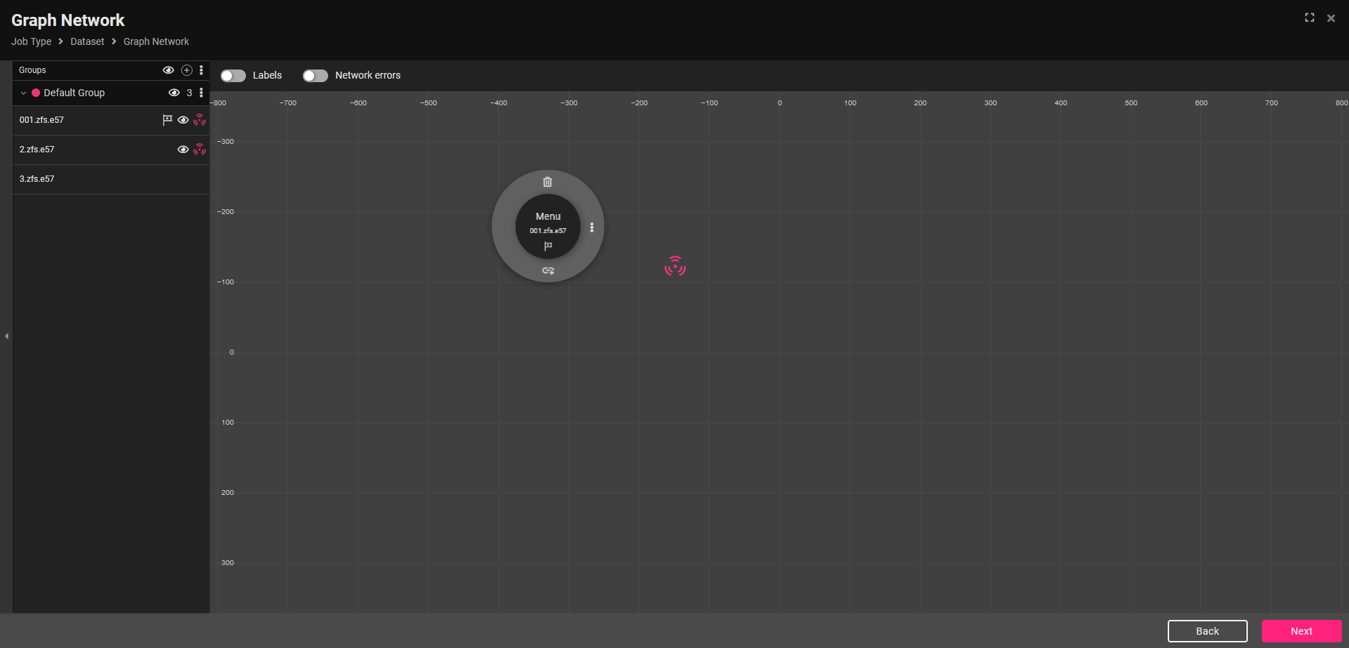
- To remove a scan from the network plan area, select it, a radial menu will pop-up, then select the bin, then the check-mark to remove it.
Connect Scans
- All scans need to be linked to be valid and loops are allowed
- To connect scans:
- Click on a scan in the plan area and a radial menu will pop up.
- Select the link icon at the bottom of the radial.
- This will put you in link mode. Select another scan visible in the plan area to create a link.
Network Errors
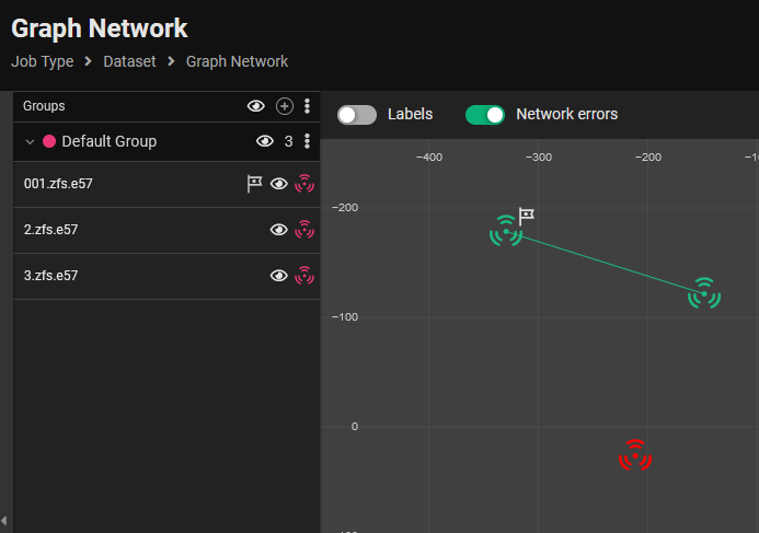
If ‘Network errors’ is toggled on in the top menu then the colour scheme will change to highlight any errors in the network in red.
This ensures the network is valid and contains no disconnected scans. The below image shows an example of an erroneous disconnected scan being highlighted in red:
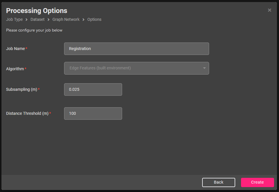
Settings
With the network complete the last stage is to set the Processing Options, including job name and basic processing parameters.
Algorithm: This setting is used to select the appropriate processing algorithm for the data provided.
- Edge Features (built environment) – If it is mainly built environment data where a lot of hard edges are found such as beams, walls, corners or doors.
- Plan View (natural environment) – If the scene contains natural elements with vertical features such as found in mines or tunnels.
Subsampling: the minimum distance between points. This evens out the spacing of points in the scans to avoid bias from the dense amount of points close to the scanner. A smaller figure increases processing time.
Distance Threshold: the maximum point distance from the scanner to use in the registration. Longer range scans may require a larger value here to take into account more common features at range.
Once set, click Create to send the auto registration job for processing.
Auto Registration Quality Report
Once the job has finished a report will be calculated for QA checking. You can view a full breakdown of the statistics of the auto-registration in this job report. We generally recommend running an Optimise Registration to get the highest quality result after an Auto Registration result (assuming no manual correction is needed first).
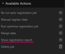
To access the report, choose Show registration report from the right sidebar for the Auto Registration job.
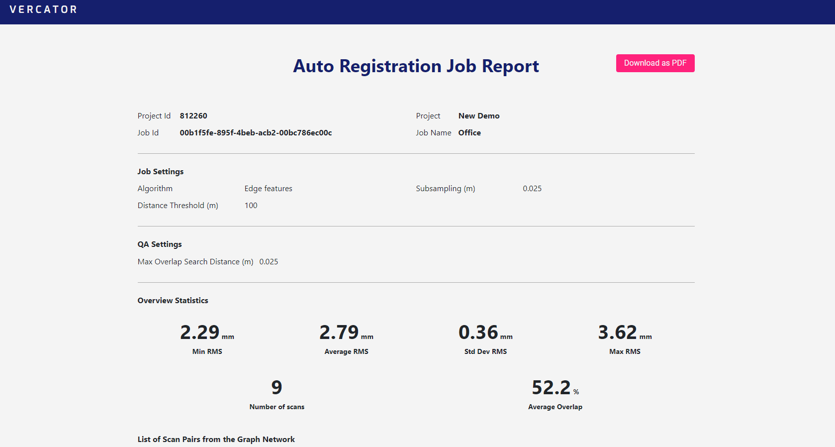
This will open the report in a new window. This report can be downloaded as a pdf, you can view a sample report here.
The report is broken down into some top level details such as overall average accuracy (RMS error) and overlap. Then a list of the scan pairs, their individual errors and overlap used for traceability and identifying problems.
Export
The result can be exported unstructured by first running a merge or, if the data is supported, it can be exported as structured data as described here.