

Knowledge Base & Support
TOPICS
Network Creation
This article explains building the scan network, the concept behind the network pairs and how they are defined in setup of a job.
Currently the registration algorithm must be told which pairs of scans to use for registration (in practice, the scans would contain overlapping regions of the scanned scene). This information is provided to the algorithm by the user through the scan network tool during project setup. This process is easiest done by recording the rough placement of scans in the field using the Vercator App, which will allow the import.
Interface
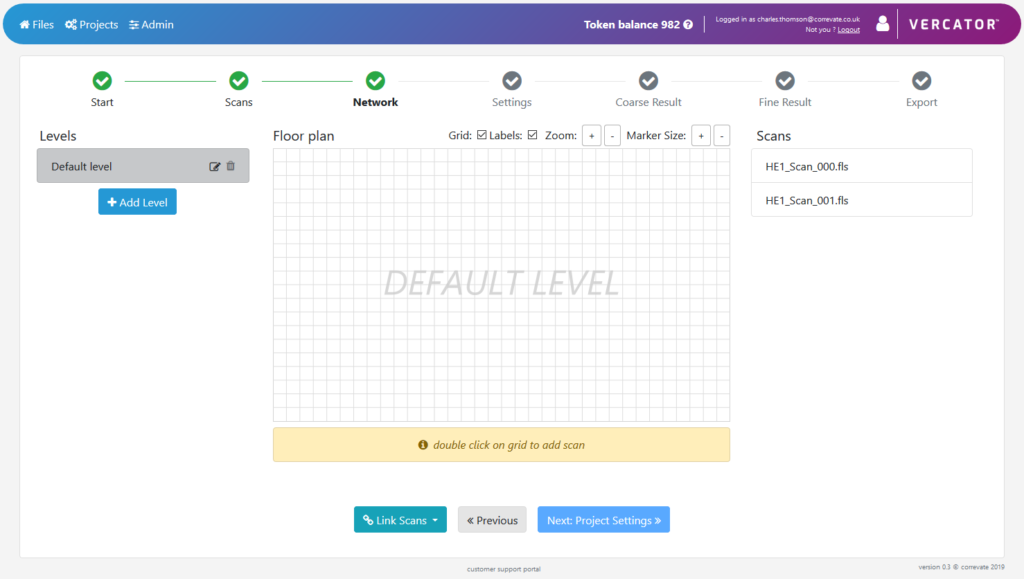
The network interface is split into three elements, from left to right:
- Levels – for managing different layers of the scans such as floors in a building. Here levels can be named, deleted or edited to add a custom background image.
- Floor plan – the canvas area on which scans are placed. This can be schematic and does not need to be spatially correct. Under this canvas is a status tip box giving advice.
- Scans – a list of the scans in the project to be placed. These fade to grey when placed in the network.
Creating the Network
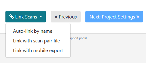
Scans can be either manually added to the canvas or automatically added by clicking the Link Scans option and selecting Auto-link by name or Link with scan pairs file.
Manual placement instructions appear in the status box below the canvas but scans can be either dragged in from the list or placed by double-clicking on the canvas.
Links can then be created by right-clicking on a scan and dragging to another scan that has overlap as below. To link between levels right-click on a scan -> Connect To -> [Level Name] -> [Scan Name]
All scans need to be linked and loops are allowed. The registration algorithm will add loops that it finds itself as well in fine registration.
Automatic placement can be performed in three ways currently:
- Auto-link by name – links scans sequentially by their name alphanumerically. These can then be edited in the canvas if required.
- Link with scan pair file – this requires a csv file formatted as one pair per line e.g.
scan001.ptx, scan002.ptx
scan002.ptx, scan003.ptx
- Link with mobile export – this requires a zip file generated from the Vercator mobile field app uploaded from your local computer.
Scan Pairs Concept
The linkages between scans when building the network must conform to certain rules as described in this section. Below is an example of building the network:
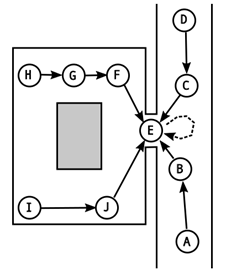
Consider the scene shown above. This consists of a room connected to a corridor, with some obstruction in the centre of the room. Ten scans whose locations are indicated by the circles with letters A-J are taken, where E is the home scan. The arrows connecting the circles show the pairwise scans used for registration and the connections chosen between them to form the network following the rules below. Scans H to I could also be linked to form a loop for redundancy and error correction.
Scan Pairs Rules
– All scans must form a single network with one or more branches. No disconnected scans allowed.
– The user-defined network can contain loops; the fine registration algorithm itself will add & solve loops it finds as well as user defined ones.
– The network must contain one root or home scan (scan E in the above example). This is the global origin. Ideally this should be fairly central to the network so that the branches of the network are fairly equal. This is calculated automatically (except when using the API) but can be forced by the user if needed.